Storing and delivering energy
You take off a mechanical watch on Friday evening. It continues running on the table. Your arm is no longer moving, and nobody is turning the crown, yet the hands advance through the night. Somewhere inside the case, an earlier action has left the mechanism with energy it can use later.
That separation between receiving energy and spending it makes a portable mechanical watch possible. Its mainspring stores energy while being wound and delivers energy as it unwinds. The watch then distributes that energy through an arrangement of wheels, bearings, and regulating parts. Understanding this route explains what winding does, what a power-reserve specification means, and why a watch can stop even though its hands look undamaged.
We will use a conventional mainspring barrel and lever-controlled train as our functional model. Particular movements arrange the wheels differently, and some use more than one barrel. The model shows relationships rather than a dismantling sequence. Keep the case closed; the questions in this chapter can be answered from a diagram and a manufacturer manual.
Two springs with different jobs
A mainspring is a long, thin strip of spring material wound into a compact space. Its elastic deformation stores energy. The much finer balance spring, also called a hairspring, works with the balance wheel to establish an oscillation. Both are springs, but a description that swaps their jobs produces a watch that makes no mechanical sense.
Think about the consequences of removing the distinction. If the mainspring itself were the accurate oscillator, winding it would need to produce a precisely repeated timing event. Instead, winding changes the energy available to run the movement. The balance can make many thousands of beats while the mainspring gradually unwinds through a comparatively small number of turns.
Elastic storage means that the spring's deformed state matters. You do work while winding: a force acts through motion, transferring energy into the mechanism. During operation, the spring moves toward a less tightly wound state and can do work on connected parts. Energy is not created when you let go of the crown. You supplied it earlier.
The distinction also clarifies the phrase “self-winding.” It describes an arrangement for obtaining winding energy from movement of the watch relative to an internal weight. The watch does not supply its own unlimited energy. If it receives too little winding input over time, its stored reserve diminishes and it will eventually stop.
Look inside the functional barrel
The barrel is the drum that houses the mainspring. An arbor is the central shaft around which the spring is wound. In a conventional going-barrel arrangement, the inner end of the spring is attached to the arbor and the outer end is coupled to the barrel. Winding turns the arbor relative to the barrel, increasing the spring's stored energy. During running, the spring drives the barrel, whose outer teeth engage the train. FHH: barrel
This account describes the ordinary functional arrangement, not every historical construction. The important relationship is relative rotation between the spring's ends. If you only imagine the whole assembly turning as a rigid lump, you have lost the deformation that stores energy. The arbor, spring, and drum have different roles even though they occupy one compact assembly.
A manufacturer parts drawing can help you identify those roles without teaching you how to service them. The Seiko 4R35B/4R36A technical guide separately identifies a barrel complete with mainspring, the center wheel, intermediate train wheels, escape wheel, pallet arrangement, and balance assembly. It also distinguishes the automatic-winding components from the going train. Seiko: 4R35B/4R36A technical guide
The barrel does not pour a substance called time into the rest of the watch. It applies torque: a turning effect about an axis. Energy is transferred when that torque acts through angular movement. A wheel can be held stationary while torque acts on it; when the escapement permits movement, the train advances and transfers energy. Force, movement, and timing are related but separate features of the event.
Follow manual winding
The crown is the external control commonly used for winding and setting. A stem connects it to internal components. In the appropriate winding position, turning the crown engages a route that winds the mainspring. A retaining arrangement prevents the wound spring from simply driving the winding controls backward as soon as you release them.
The crown can also have other positions that engage setting functions. That is why “turn the crown” is not a complete operating instruction. Which position, which direction, and whether a screw-down crown must first be released depend on the watch. This chapter explains the energy route; the exact manual governs how an actual watch should be handled.
The Seiko 6R55/6R5J manual describes automatic winding supplemented by manual winding through the crown. It also states that winding in the opposite direction does not wind that movement. These are useful examples of why an apparently familiar control needs movement-specific instructions. The manual's operating directions should not be transferred to an unidentified watch. Seiko: winding the 6R55/6R5J
Setting and winding therefore answer different needs. Winding restores available energy. Setting establishes what the display indicates at the start of subsequent running. A watch may be fully wound and set to the wrong hour. It may also be correctly set but close to the end of its reserve. One action does not certify that the other has been completed.
How movement becomes winding
Many automatic movements use an off-center rotating mass, usually called a rotor or oscillating weight. As the watch changes orientation or moves, the weight can rotate relative to the movement. A winding mechanism converts some of that relative motion into winding of the mainspring. The useful input is mechanical work delivered through that route.
The rotor does not have to turn at the rate indicated by the seconds hand. Its movement responds to wearing conditions. The timing mechanism must continue to maintain the watch's pace whether the rotor is briefly moving, still, or changing direction. Energy storage separates irregular input from the relatively steady requirements of timekeeping.
Different automatic mechanisms use different ways of handling rotor direction. Seiko's museum explains its Magic Lever as a mechanism in which an eccentric connection moves a lever whose two working tips alternately pull and push a transmission wheel. The result converts motion associated with either rotor direction into one winding direction. That is one documented design, not the definition of all automatic winding. Seiko Museum: the Magic Lever
Imagine an invented daily energy account. The watch uses ten arbitrary energy units in a day. Your activity supplies twelve through its winding mechanism on one day and four on the next. Before allowing for a full-store limit, the net changes are plus two and minus six. Wearing the watch on both days does not establish equal winding input. No numerical values here describe a particular wristwatch or activity level.
When the store is full, a movement needs a design that handles further winding input. Many automatic constructions use a slipping attachment associated with the mainspring barrel; hand-wound designs can behave differently at full wind. The British Horological Institute explains this protective slip in its technician lesson. A statement that one identified movement tolerates continued crown turning is not permission to force another. You can understand the design problem without testing it on the object. BHI: Lesson 10, section 17.6
Wheels trade speed and turning effect
A large toothed wheel engaging a smaller pinion can make the smaller part rotate several times for each turn of the larger. A pinion is a small toothed member, often sharing an arbor with a larger wheel that drives the next stage. Successive stages allow a slowly moving barrel to drive faster-moving parts of the train.
The increase in rotational speed does not create energy. In an ideal lossless pair, a gain in speed comes with a corresponding reduction in delivered torque. Real teeth and bearings introduce losses, so the useful energy emerging from the pair is smaller than the energy supplied. The train is an arrangement for transmission and ratios, not a source of additional power.
Consider an original simplified pair. A 60-tooth driving wheel engages a 12-tooth pinion. One complete turn of the wheel carries sixty teeth past the contact. The pinion must make five complete turns to pass the same number: 60 ÷ 12 = 5. For external gears their rotation directions are opposite. These counts are invented teaching geometry, not the train of a named movement.
Suppose the large wheel supplies a constant torque of five arbitrary torque units. In the ideal pair, the small pinion supplies one unit while turning five times as far. The product of torque and angular travel remains equal. Adding realistic losses reduces the available output further. A claim that gears multiply both speed and useful torque without another energy input would violate this account.
This helps explain why small mechanisms are demanding. The energy reaching the fast-moving end of the train must be sufficient to sustain the oscillator through the escapement while other parts also consume energy. Making wheels smaller or increasing their speed is not an isolated improvement. The movement must still deliver enough energy through the whole route.
Holding parts in the right relationship
Wheels rotate on arbors supported by the movement's structure. The main plate provides a foundation; bridges and related supports hold components in their intended positions. These apparently stationary parts matter because the positions and clearances determine whether teeth and bearings can work as designed.
Friction at contacts and bearings transfers some organized mechanical energy into thermal motion. Lubrication and suitable bearing materials help control friction and wear at designed locations, but they do not eliminate all loss. A movement's visible operation is the result of these many contacts working together. A part count alone says little about how effectively that happens.
Jewels in a movement often serve functional bearing or contact roles. Seiko's museum describes their use at rotating shafts and escapement contacts. Their purpose should be identified from the mechanism rather than interpreted as jewelry hidden inside a watch. More jewels need not establish a more accurate oscillator, a longer reserve, or better execution. The count has meaning in relation to the actual construction. Seiko Museum: functional stones
This is also why “it needs more oil” is an inadequate response to unexplained behavior. Correct servicing concerns specified materials, quantities, locations, cleanliness, condition, and assembly. An owner cannot infer those requirements from a slowing hand. Our diagrams follow energy and function; they do not turn an observed symptom into a repair instruction.
What a power reserve measures
Power reserve is the operating duration available from the specified winding state, commonly full wind to stopping under stated conditions. It is a duration rather than a direct measurement of stored energy. Two movements with similar reserves may store different amounts of energy and consume it at different rates.
If an imagined mechanism has 100 usable energy units and consumes two units per hour at a constant rate, its simple reserve is fifty hours. A second stores only sixty units but consumes one per hour, giving sixty hours. The second lasts longer despite the smaller store. This deliberately simplified calculation separates capacity from consumption; real watch consumption and available torque need not stay constant throughout a run.
The watch also needs enough usable torque for its mechanism to continue operating. A stopped movement need not contain a perfectly relaxed spring with literally no stored elastic energy. Some energy may remain that cannot sustain operation through the relevant loads and losses. “Empty” is a convenient description of the useful reserve, not a complete physical description of the spring.
Epson's account of its mechanical movements describes a power-reserve indicator as a mechanism intended to show remaining operating time. It also connects later changes in escape-wheel construction with changes in driving efficiency and duration. Those are manufacturer descriptions of its designs, useful for seeing that reserve involves the whole movement. They are not independent comparisons of all watchmakers. Epson: mechanical watch design
Duration cannot settle a timing question
Suppose a hypothetical watch runs for seventy hours after full winding. During the first day it gains three seconds; during the second it loses eight. Its measured duration remains seventy hours, but that number has not described its changing rate. Conversely, a watch with a shorter reserve could show more consistent rate over the interval tested.
The spring's state can influence the energy supplied to the regulating system. The designer must manage how the balance and escapement behave as operating conditions change. An ideal oscillator would preserve its period even when its swing size changed. A real mechanical watch only approximates that ideal, which is one reason a reserve claim should not be silently converted into a precision claim.
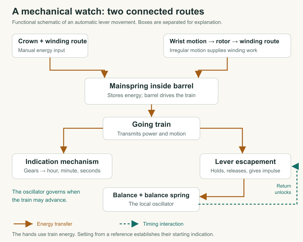
You now have a route with identifiable responsibilities: an external action provides winding work; the mainspring stores energy; the barrel and train transmit it; the hands, contacts, and oscillator require it. The remaining mystery is how the powered train is allowed to advance at a useful pace. To answer that, we must watch the escapement alternately hold, release, and sustain the balance.
Application
Trace the energy without opening a watch
Make a diagram of a conventional automatic mechanical movement using these labels: wrist motion, rotor, automatic-winding mechanism, crown and winding route, mainspring in barrel, going train, hands, escapement, and balance with balance spring. Show two alternative routes into the mainspring and the principal operating routes out of it. Mark the drawing as functional, not a parts layout.
Explain why the rotor can remain still while the hands continue moving. Then identify the error in this fictional description: “The rotor spins the balance at the right speed, the hairspring stores several days of energy, and the gears multiply the energy so the hands can move.”
Make a bounded energy account
Use the invented 100-unit store consuming two units per hour. It begins full, runs for twelve hours without winding, receives ten usable units, and then runs for another eight hours without winding. Assume constant consumption, no capacity overflow, and no other inputs. Calculate the remaining energy and simple remaining duration.
A seller then calls this a “50-hour accurate watch.” Explain which part of that phrase your calculation supports and which needs separate evidence. Consult the linked manual for the winding procedure of one identified movement, but do not perform it on a different watch.
Model interpretation
The crown route and rotor route both provide winding input to the mainspring. During running, stored energy passes from the barrel into the train, reaches the indication mechanism, and reaches the balance through the escapement. The rotor's motion is not the time reference. Storage allows operation to continue between winding inputs.
The fictional description substitutes the balance spring for the mainspring and assigns the rotor a timing function it does not perform. Gears transmit energy with losses while changing speed and torque relationships; they do not multiply the available energy.
The account is 100 − 24 + 10 − 16 = 70 units. At two units per hour, that gives thirty-five further hours under the model assumptions. Fifty hours describes the original full-store duration in this model. It does not establish the accuracy of elapsed-time indication, rate consistency, or performance of any actual watch. Those require a reference comparison and specified observation conditions.